
Screw caps, droppers and closures
Discuss this requirement as part of your machinery specification.
Machinery
Capping machinery for tightening and applying closures consistently across repetitive packing operations.
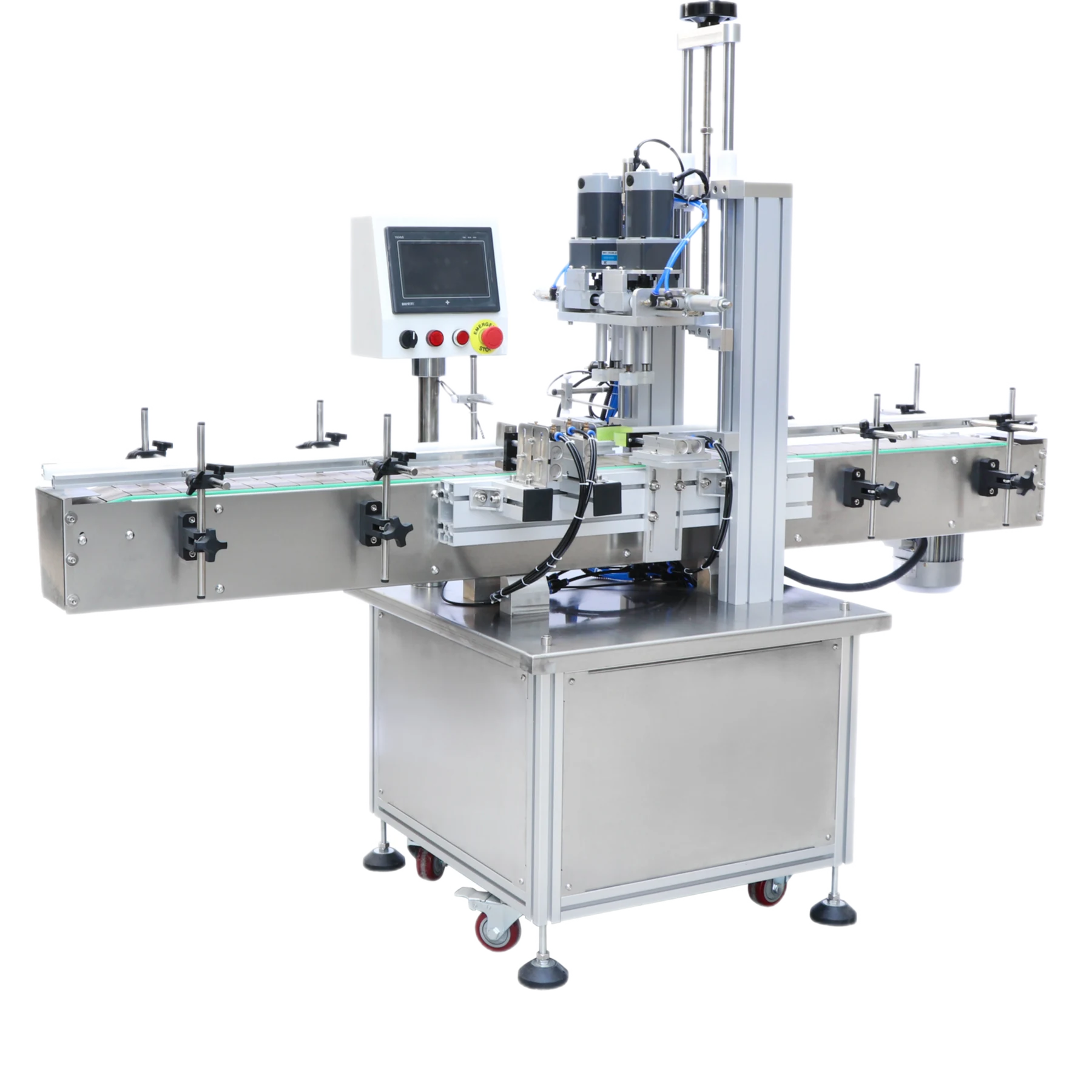
Machinery page
Capping machinery for tightening and applying closures consistently across repetitive packing operations.
Next step
Provide the product, packaging format, current process and the level of automation you want to achieve.
Discuss this requirement as part of your machinery specification.
Discuss this requirement as part of your machinery specification.
Discuss this requirement as part of your machinery specification.
Capping machine selection
Reliable capping depends on more than tightening. Closure presentation, bottle support, cap placement, thread engagement and verification all need to suit the real components.
Provide matching cap and container samples. Thread form, tamper features, liners, pumps, triggers, droppers and overcaps can require different presentation and tightening methods.
Bottle height, base shape, wall strength, neck support and fill level affect how the pack can be held while the closure is placed and tightened.
Define what an acceptable closure looks and feels like, how it is checked, and whether orientation, torque, seating, tamper evidence or leak performance must be reviewed.
A capping process may include bulk cap feeding, orientation, transfer, placement, thread engagement or pressing, and a final tightening or seating action. Some applications retain manual cap placement and automate only the tightening stage. Others require automatic cap sorting and delivery because closure handling is the main production constraint.
The container must remain controlled while the closure is applied. Side belts, guides, star wheels, neck handling or other supports may be considered depending on pack shape and the capping principle. Filled product behaviour also matters: an open container may spill, foam or become unstable if acceleration and transfer are too abrupt.
Changeover should cover cap guides, chutes, heads, bottle supports and sensor positions. Where several closures are in scope, identify the normal and most difficult examples and explain how often formats change. A component trial should confirm that the closure feeds, lands and tightens without damage before a final line arrangement is agreed.
Different closure families can need different machinery principles. A screw cap, press-on lid, pump, trigger, dropper, cork or crimped component should not be treated as the same application. Manual placement with assisted tightening may also be more practical than full cap feeding for low-volume or frequently changing work.
For model-level closure machinery, see the Lancing capping machinery range. Project details can be sent through the sales enquiry page.
Buyer questions
Component samples and a defined finished condition are central to each answer.
Screw caps, pumps, triggers, droppers, lids and other closures may be handled, but each family needs its own review of orientation, placement, tightening and container support. Samples are essential.
A torque value does not show whether a cap has cross-threaded, seated correctly, damaged a liner or reached the intended position. The acceptance method should consider the complete finished closure.
It is most relevant when cap orientation and supply are repetitive constraints and the closure can be fed reliably. Low volumes, frequent format changes or delicate closures may favour manual placement with assisted tightening.
An unstable, flexible or tall container may need additional support while the cap is applied. The fill level and product movement can also affect how quickly the container can be transferred.
Possibly, where the capping principle and component ranges are compatible. Change parts, guide adjustments, head settings and cap feeding must be reviewed for each format.
Test representative containers and closures, including the most difficult format, and agree how feeding, placement, finished condition and sustained operation will be assessed.
Closure process control
Bottle capping machines are easier to specify when every closure-handling step has its own incoming condition, adjustment method and acceptance check.
Closures must reach the placement point in a usable orientation without nesting, bridging or damage. Bulk behaviour, component finish and any dip tube or tamper feature should be represented by production samples.
The closure should meet the neck squarely and at the correct time. Bottle position, cap release, thread engagement and support during the first contact influence the result before tightening begins.
Define the acceptable seated position, orientation, tamper feature and pack condition. The check should identify cross-threading, missing components or visible damage as well as insufficient or excessive tightening.
A cap feeder can deliver closures correctly while an unstable bottle arrives late or off centre. Equally, a tightening head can be set correctly while a closure is released at an angle. The review should follow the component from bulk supply through orientation, transfer, placement, engagement and final release, then identify which step is manual and which is automatic.
Filled-container behaviour matters throughout this sequence. Product in the neck, a flexible bottle wall or movement of liquid inside a tall pack can change how firmly the container can be restrained. Transfer from filling machinery should therefore be considered with bottle support and the available time before capping. The discharge must also present a stable closed pack to labelling equipment.
Several cap diameters do not automatically form one compatible family. Record thread style, height, liner, tamper band, grip surface, top profile and any pump, trigger, dropper or dip-tube feature. Identify which components can share the same placement and tightening principle and which require a different head, guide, feeder track or manual operation.
For each family, document the changeover settings and the evidence used to approve the first finished packs. A representative run should include normal replenishment and a restart after a short stop, because component queues and bottle spacing can change during recovery. The conveyor and handling review should define blocked and starved conditions around the capper.
Use the project brief to separate required functions from optional automatic cap feeding, and include complete matched container and closure samples with the enquiry.
Closure project resources
These guides help compare manual and automatic closure handling, connect the capper to the line and test the most difficult component combinations.
Separate cap orientation, placement and tightening so the retained operator work remains visible.
Define cap-present checks, bottle detection, blocked and starved signals, reject confirmation and restart behaviour.
Record component lot, placement, bottle support, tooling, settings and observed finished condition.
Closure questions
The cap, container finish, placement method and tightening method form one closure process.
The suitable capping machine depends on whether the closure is screw-on, press-on, pushed-in or otherwise applied; how it is presented; the container finish; required tightening control; container support; and the production pattern. A mechanism suitable for a stable screw cap may not suit a delicate pump, T-cork or snap closure.
Compare the main mechanisms in the capping machine types guide and confirm with production samples from the actual closure supply.
Caps can cross-thread or tilt when placement is not square, the cap or neck finish varies, the container moves under load, the closure is released too early, the tightening head is misaligned or the speed does not allow the thread to engage. The root cause may begin before the tightening stage.
Separate feeding, placement, support and tightening during diagnosis. The capping troubleshooting guide explains how to identify the stage responsible.
Capping torque should be based on the closure and container supplier's requirements, the product and seal system, opening performance and verified finished-pack checks. The machine setting is not the same as measured removal torque, and the relationship can change with closure material, time and test method.
Agree the application and verification method before acceptance. Avoid transferring a setting from a different cap or bottle without evidence.
Automatic cap feeding is required when the production method cannot rely on an operator presenting each closure consistently and the cap can be oriented, accumulated and delivered without damage. Feeding suitability depends on cap geometry, stiffness, decoration, nesting behaviour and the range of closures.
A semi-automatic capper may still be the better choice for low-volume, high-variation or difficult closures. Include cap-feeder replenishment and changeover in the comparison, not only the tightening cycle.
Closure path
A capper cannot apply a closure consistently if the feeder, track or transfer delivers damaged, incorrectly oriented or unstable components.
Define how closures arrive, how they are separated, what establishes orientation and how the capper receives them. Pumps, triggers, tamper bands, liners and flexible features can change feeding behaviour even when the outside diameter appears similar.
The container and closure feeding guide covers bulk presentation, singulation and queue control. The pack specification guide explains drawings, approved packs and finished closure criteria.
Cap feeding affects capping output because the application head can work only when correctly oriented closures arrive at the required time and condition. An intermittent feeder, full chute, damaged closure or missed escapement can become the limiting process even when the capping head itself has capacity.
A capping machine may support manual placement, automatic feeding or a staged combination when the application method and controls are designed for those modes. Define operator work, queue capacity, permissions and the future interface before ordering so the staged arrangement does not require an unplanned redesign.
Closure-specific machinery
Specialist closures should be specified as a bottle-and-component system. ROPP caps are formed on the bottle finish, pumps and triggers include dip tubes and orientation requirements, while induction sealing depends on the container, cap and liner remaining compatible and correctly seated.
Each route has different feeding, placement, support and quality checks. A closure name alone is not enough to select tooling.